Authors: Phil Ellis, Applications Engineer, Manchester and Shawn Zhang, Applications Engineer, Shanghai
This interactive application note contains embedded Cloud based simulations to augment the text.
To open the embedded simulation, simply hover over the simulation image. Left click anywhere in the graphic area once the central play button changes in colour. This opens the schematic in the Cloud environment. See the interactive application note tutorial page for more details on how to use the simulations.
See accompanying application note AN50016.
Introduction
Supplement Restraint System (SRS) is a high technology safety system used in most new cars nowadays. It consists of the driver airbag, passenger airbag, side airbag curtain and other airbags depending on the installation location and requirements. For example, the visual appearance of steering wheel with an airbag fitted does not suggest that this safety feature is present however in the event of a severe impact, the airbag will deploy from the steering wheel in a few milliseconds and provide a cushion between the steering wheel and the driver. This prevents the driver's head and chest from hitting the steering wheel. In the USA airbags have saved around 50,000 lives between 1987 and 2017 [1].
SRS is a very complex system, including sensors, microcontroller units (MCU), air bags, squib drivers and power supplies. The sensors and MCU are used to judge the severity of the crash, transmit and send signals, typically, it needs 10 to 15 ms between the start of the impact and activation of the squib driver. The squib driver fires solid fuel (NaNO3 or NH4NO3) and produces gas to inflate the airbags, which have a capacity of about 50 to 90 litres. Typically, it takes around 45 to 50 ms to inflate the airbags.
The squib driver is a critical part of the system, it needs to deploy when it is required to operate and also must not deploy when it is not required to operate [2].
The squib driver consists of a “safing” MOSFET operating in linear mode and a controller to regulate the voltage at the MOSFET source pin. The squib voltage needs to be carefully controlled to ensure that the airbag inflates correctly. Multiple squibs may fire simultaneously and the combined current can be significant. The safing MOSFET must be carefully selected as linear mode performance and peak power capability are important in this challenging application.
This interactive application note focuses on the application of the safing MOSFET in an airbag system, the airbag operating conditions will be discussed as well as the MOSFET safe operating area (SOA) curve. The performance of different MOSFET technologies will also be compared.
MOSFET operating conditions in airbag applications
Fig 1 shows a typical airbag application circuit. The supply voltage is usually 25 V to 35 V, which is provided by a boost converter operating from the 12 V car battery. The squib firing voltage is usually 15 to 20 V, which is controlled by the IC controller, this means the MOSFET drain to source voltage VDS is 10 V to 15 V.
For the safing MOSFET, two typical deployment profiles are shown below:
- Deployment Profile 1: VDS = 10 V max; ID = n × 1.35 A (2.1 ms)
- Deployment Profile 2: VDS = 15 V max; ID = n × 1.9 A (0.55 ms or 0.75 ms)
where n refers to the number of squibs, n is generally between 4 to 24 depending on the different requirements.
The individual squib current (typically 1.35 A or 1.9 A) and the pulse duration depend on the customer specification. For example, if 20 airbag squibs are used, the current flowing through the MOSFET will be 27 A to 38 A.
Simulation 1
For the given input signal, the MOSFET can’t be fully switched on due to the low gate driver voltage. The gate voltage will be above the gate threshold voltage but the MOSFET is working in linear mode in order to control the voltage applied to the airbag squibs.
In simulation 1, m1 is the safing MOSFET. zd2 is a 24 V Zener diode which is normally shorted by m2 unless the squib is fired, in which case m2 becomes open circuit allowing the safing MOSFET to act as a source follower. The voltage across the squib will be around 20 V meaning that the MOSFET VDS will be around 15 V. This circuit is used to demonstrate the stress on the MOSFET in the airbag application and is not a representation of a real airbag control system.
From the simulation it can be seen that the safing MOSFET bears a relatively large drain-source voltage and drain current at the same time, which means that the power loss is relatively high (due to operating in linear mode). During linear mode a MOSFET operates in its saturated state or saturation region, and it behaves as a (gate) voltage controlled current source. In any application the operating condition of the MOSFET must be within the SOA capability. If the MOSFET is working in the constant power region rather than in the Spirito region of the SOA graph, it would be possible to estimate the peak junction temperature of the MOSFET. Note that in the Spirito region, hotspot activity will determine the peak junction temperature, these hotspots will be at a temperature higher than the value calculated from the Zth graph or calculated by simulation using the RC thermal models.
For more information about linear mode, please refer to the application note AN50006 Power MOSFET in linear mode [3].
Safe Operating Area considerations
The safe operating area (SOA) gives an indication of the amount of power a device can safely handle before failing. It is a two-dimensional coordinate diagram of drain-source voltage VDS and drain current ID composed of a series of constraints. The voltage and current of the MOSFET operating are not allowed to exceed this area. Note that this SOA curve is made from calculated values and actual test results, with the initial mounting base temperature being 25 °C. If the actual application temperature is higher than 25 °C, derating is required, for details, please refer to Nexperia application note AN50006 [3] or AN11158 [4].
Fig 2 shows the SOA graph for the BUK9Y15-60E, which is the combination of measured behavior (especially at higher VDS values, where the Spirito effect is present) and thermal behaviour (based on Zth). It can be subdivided into 5 parts depending on the pulse duration:
- corresponding to the limit due to RDSon mode
- limited by the peak drain current
- maximum pulse power dissipation limit, where the product of Zth, VDS and ID is a fixed value and the MOSFET junction temperature can reach to Tj(max)
- limited by the VDS rating
- limit during linear mode operation, which is from measured behaviour
Figure 2. MOSFET safe operating area limiting boundaries
For a more detailed description of the SOA curve, please refer to the application note AN11158 [3].
The SOA is especially important in the case of linear mode operation, such as in airbag applications. The MOSFET is used to control the current in a resistive load (the airbag squibs) and hence the voltage across the load. In airbag applications, customers would select DMOS (diffusion MOSFET technology) or some older generations of Trench MOS in a DPAK package due to the thermal performance and good SOA. However, the supply of DPAK MOSFETs in the market is reducing as there is a trend towards newer and more efficient packages such as LFPAK56.
Fig. 3 shows a typical Nexperia MOSFET (BUK9237-55A) SOA curve used in this application, the circled area shows where most airbag squib drivers work over the ID range of 5 to 45 A and VDS of 10 to 15 V.
BUK9237-55A is a Nexperia T2 generation trench technology MOSFET in a DPAK package.
Fig. 4. shows a comparison of the BUK9237-55A using the older generation T2 technology in DPAK compared to the more modern T6 technology in LFPAK56 and LFPAK33. Here the focus is only on the 1 ms SOA curve and the red circle is the operating area for the airbag Deployment Profile 2 (≤1 ms pulse duration) application with 5 to 10 airbag squibs.
Generally, the cell pitch shrinks with more recent MOSFET technologies, allowing more trenches per mm2 and reducing the RDSon per mm2 . This means the same RDSon will require a smaller die or the same die size will have a lower RDSon.
On the other hand, the higher trench density has the opposite effect on linear mode performance. The higher the trench density, the lower the linear mode capability.
We can find some symptoms of this in Fig. 4. BUK9M12-60E (Trench 6 technology) has a similar die size to BUK9237-55A (T2 trench technology), but the linear mode performance is worse due to the increased cell density of newer trench technologies.
The RDSon is much lower but its linear mode capability is also lower. To achieve a similar or higher SOA performance, a larger die size (which gives even lower RDSon) is needed as shown with the BUK9Y4R8-40E (T6 trench technology). Note that here the packages used in Fig. 4 are different. The bigger DPAK package makes only a slight improvement to the SOA since the power pulse duration in linear mode is quite short: only 0.75 ms for Deployment Profile 2 and 2.1 ms for Deployment Profile 1. At this pulse duration, the thermal energy is mainly in the silicon die and has not reached the package yet. The choice of package has very little thermal impact on the design.
Table 1 shows Nexperia's 60 V portfolio of ASFETs for airbags. This range of MOSFETs uses Nexperia's latest generation of automotive grade enhanced SOA technology, that offers comparable linear mode performance to T2 trench technology per mm2 at the airbag operating conditions:
| Part number | RDSon(max)
@ VGS = 4.5 V |
SOA current capability
@ tp = 1 ms; VDS = 20 V |
Package |
|---|---|---|---|
| BUK9Y7R0-60EL | 7.0 mΩ | 42 A | LFPAK56 |
| BUK9Y8R8-60EL | 8.6 mΩ | 33 A | LFPAK56 |
| BUK9Y13-60EL | 12.4 mΩ | 26 A | LFPAK56 |
| BUK9Y22-60EL | 23 mΩ | 15 A | LFPAK56 |
| BUK9M20-60EL | 20 mΩ | 15 A | LFPAK33 |
| BUK9M31-60EL | 33 mΩ | 10 A | LFPAK33 |
| BUK9M67-60EL | 67 mΩ | 5.7 A | LFPAK33 |
As shown in Fig. 5, BUK9M12-60E is the product using T6 trench technology and BUK9M20-60EL uses enhanced SOA technology. These two example parts have the same die size and package, but the SOA capability is improved for the enhanced SOA product, which means it is better suited to applications like Airbag. This can be compared with the DPAK Trench 2 type shown in Fig. 4.
At a VDS of 15 V the BUK9M20-60EL has a 1 ms capability of 20 A, whereas the BUK9M12-60E has a capability of 12 A, shown by the circled area.
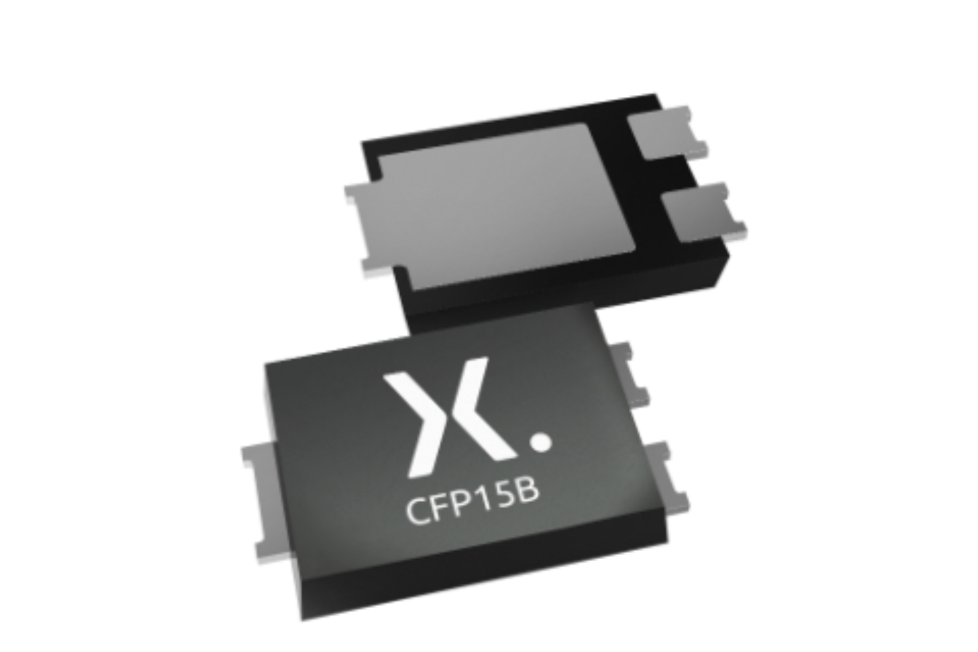
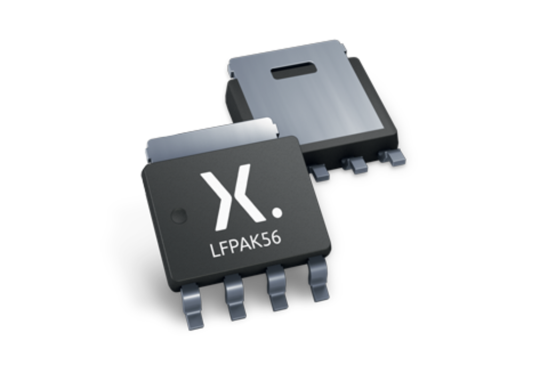
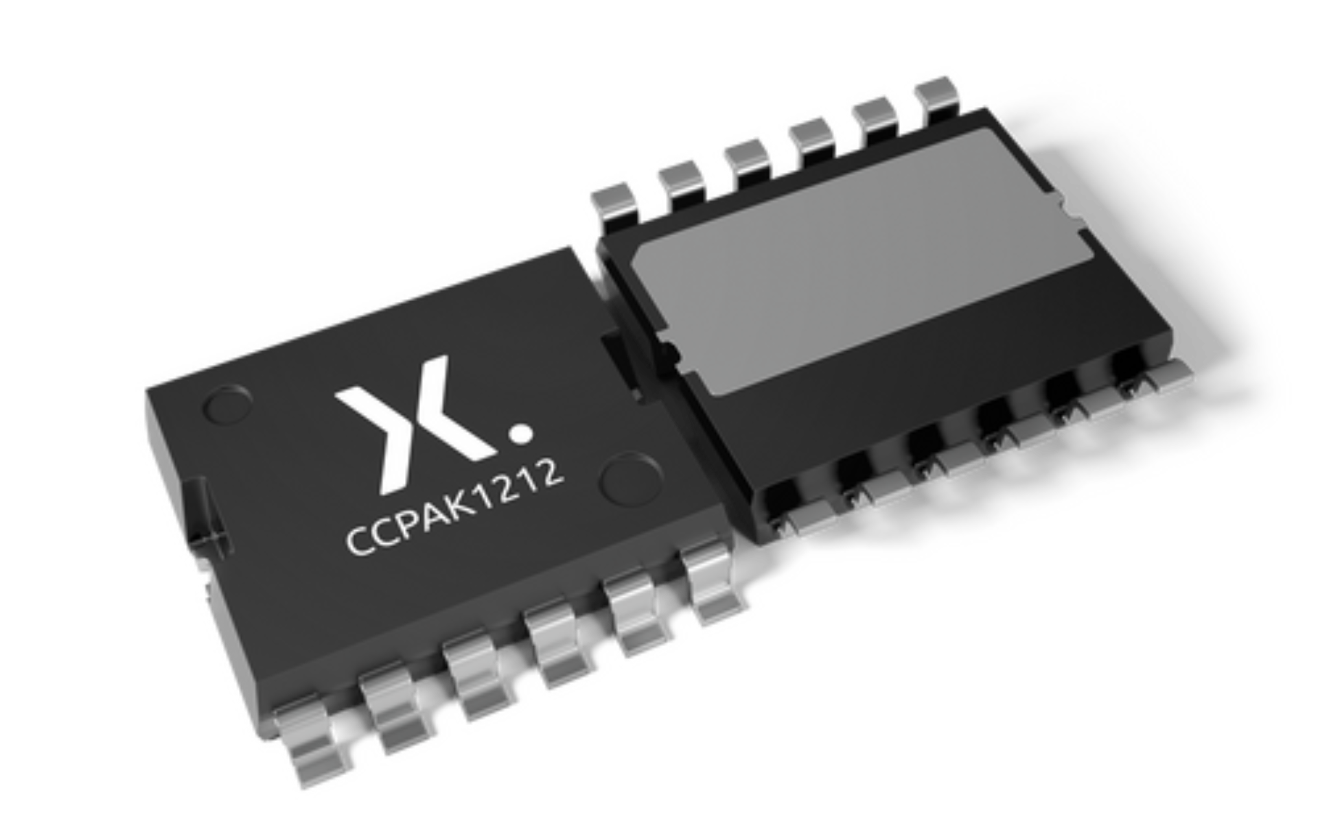
The part number ends with “L”, this indicates that it is an enhanced SOA MOSFET. LFPAK33 and LFPAK56 packages are used for more modern Nexperia power MOSFET products. The LFPAK packages are smaller than DPAK while achieving similar SOA performance. The LFPAK family of packages not only offers a more reliable and sustainable alternative to DPAK, but also offers up to 84% saving in PCB area.
References
- United States Department of Transportation: https://www.nhtsa.gov/equipment/air-bags
- Bosch Automotive Handbook 10th Ed pp1182-1189, John Wiley & Sons, 2018
- AN50006 Power MOSFETs in linear mode, Nexperia
- AN11158 Understanding power MOSFET data sheet parameters, Nexperia
Summary
In this interactive application note, the airbag operating conditions and safing MOSFET performance are analyzed. The safing MOSFET in the airbag application operates in linear mode and bears a large current and voltage at the same time, so the MOSFET SOA curve must be considered. The SOA curve of Nexperia T2 trench technology, T6 trench technology and enhanced SOA technology products have been presented and compared. Nexperia enhanced SOA products have better SOA performance compared with T6 trench technology of the same die size and have comparable linear mode performance to older T2 trench technology per mm2 at the operating condition of many airbag applications.
For more details on the Nexperia ASFETs for airbag portfolio, please see: Automotive ASFETs for Airbag Applications.
MOSFETs in automotive airbag applications
The forgotten MOSFET in automotive airbag applications – Quick Learning
| Page last updated 24 May 2022. |
