


- Block diagram
- Design considerations
- Design resources
- Product listing
- Support
Block diagram
Highlighted components are Nexperia focus products.
Battery management
Bidirectional DC buck / boost
Recommended products (8)
- DC-DC converters: 4.5 V to 40 V, 600 mA
- Transformer drivers: low-noise, 1.2 A
- Schottky diodes: 40-100 V, 1-5 A, CFP
- 48 V battery - GaN FETs: 100-150 V, e-mode
- 48 V battery - MOSFETs: 60 -100 V
- 400 V battery - Gan FETs: 650 V, cascode
- 400 V battery - Gan FETs: 650 V, e-mode
- 800 V battery - SiC MOSFETs: 1200 V, 17-80 mΩ
Hotswap / backplane protection
Recommended products (2)
Aux power supply driver
Recommended products (8)
- DC-DC converters: 1.8-5.0 V
- LDO regulators: 40 V, 150 mA
- Power distribution: Load switch, 5.5 V, 55 mΩ
- Zener diodes: 500 mW, SOD123F
- Low VCEsat transistors: ±40 V, ±0.5 A, DFN
- Schottky diodes and rectifiers: 40-100 V, CFP
- Voltage regulator diodes: DFN1006
- MOSFETs: 40-100 V, RDSon 5-15 mΩ, LFPAK / MLPAK
Gate driver
Signal processing
Communication Interface
Recommended products (2)
Power Distribution unit (PDU)
Related applications (1)
Select a component
To view more information about the Nexperia components used in this application, please select a component above or click on a component (highlighted in blue) in the block diagram.
Design considerations
- Ideal Diodes vs. Schottky: For higher efficiency and lower heat generation, use Nexperia’s integrated ideal diodes (like the NID5100 or NID1100). These provide the low power loss of MOSFETs with the reverse current blocking of traditional diodes, crucial for seamless power ORing.
- Isolation MOSFETs must handle massive energy discharges during fault conditions. Nexperia recommends ASFETs (Application Specific MOSFETs) with strong SOA performance to operate safely until the battery is isolated.
- Use load switches with adjustable current limits (110 mA to 2.5 A) and active reverse current blocking to protect the upstream system from damage.
- Implement high-robustness ESD protection with low dynamic resistance and low capacitance (such as TrEOS technology) to maintain signal integrity on communication lines.
- Use Nexperia's electrothermal MOSFET models during the preliminary design stage to accurately simulate dynamic characteristics and avoid late-stage EMI issues (AN50012).
- For the Battery Management Systems use external MOSFETs for active or passive cell balancing in high current systems and : Integrate Zener diodes in the balancing stage to protect both the FETs and the individual battery cells
Design resources
Evaluation boards
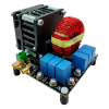
NX-HB-GAN111-650WSB - 400 V, 2 kW GaN FET half-bridge evaluation board
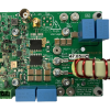
NX-DP-GAN039-650NBB - 650 V GaN FET (bottom-side cooled) double pulse evaluation board
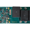
NEVB-HB-NSFD7-A - 1200 V SiC MOSFET (TO-263-7 ) double-pulse half-bridge evaluation board
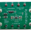
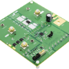
NEVB-NEX90530BPA-Q100 - 3-40 V, 300 mA ultra-low Iq LDO evaluation board
NEVB-LOGIC04 - DIL footprint (XSON / DHXQFN) adapter board
Reference designs
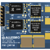
Allegro AHV85110 evaluation board
Analog Devices EVAL-LTC4286-A1Z Hotswap
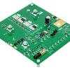
Analog Devices EVAL-LTC4287 54 V, 72 A Hotswap
Microchip MIC2129 48-to-12 V power conversion
Product listing
Battery management
Bidirectional DC buck / boost
- DC-DC converters: 4.5 V to 40 V, 600 mA
- Transformer drivers: low-noise, 1.2 A
- Schottky diodes: 40-100 V, 1-5 A, CFP
- 48 V battery - GaN FETs: 100-150 V, e-mode
- 48 V battery - MOSFETs: 60 -100 V
- 400 V battery - Gan FETs: 650 V, cascode
- 400 V battery - Gan FETs: 650 V, e-mode
- 800 V battery - SiC MOSFETs: 1200 V, 17-80 mΩ
Hotswap / backplane protection
Aux power supply driver
- DC-DC converters: 1.8-5.0 V
- LDO regulators: 40 V, 150 mA
- Power distribution: Load switch, 5.5 V, 55 mΩ
- Zener diodes: 500 mW, SOD123F
- Low VCEsat transistors: ±40 V, ±0.5 A, DFN
- Schottky diodes and rectifiers: 40-100 V, CFP
- Voltage regulator diodes: DFN1006
- MOSFETs: 40-100 V, RDSon 5-15 mΩ, LFPAK / MLPAK