


Nexperia's Interactive application notes provide general guidelines for various power designs and topologies. A simulator is embedded inside the application with a predefined schematic. This simulator provides a direct view of the performance from system level down to individual component level.
Navigating to Interactive application note pages
To access the interactive application note pages, you can navigate from the ‘Applications’ tab on the Nexperia main website page. Scroll down to the last section of that page to find the ‘Interactive application notes’ section. By clicking on one of the interactive application notes, you will gain full access to the text of the system description which include embedded simulations.

Figure 1. Navigation to the Interactive application notes
Using the embedded simulator
Take IAN50001 - Reverse battery protection in automotive applications as an example to show how to use the embedded simulator. To open the embedded simulation, simply hover over the simulation image. Left click the start icon  or the Open Design Analyzer button to see the simulation result of the designed circuit.
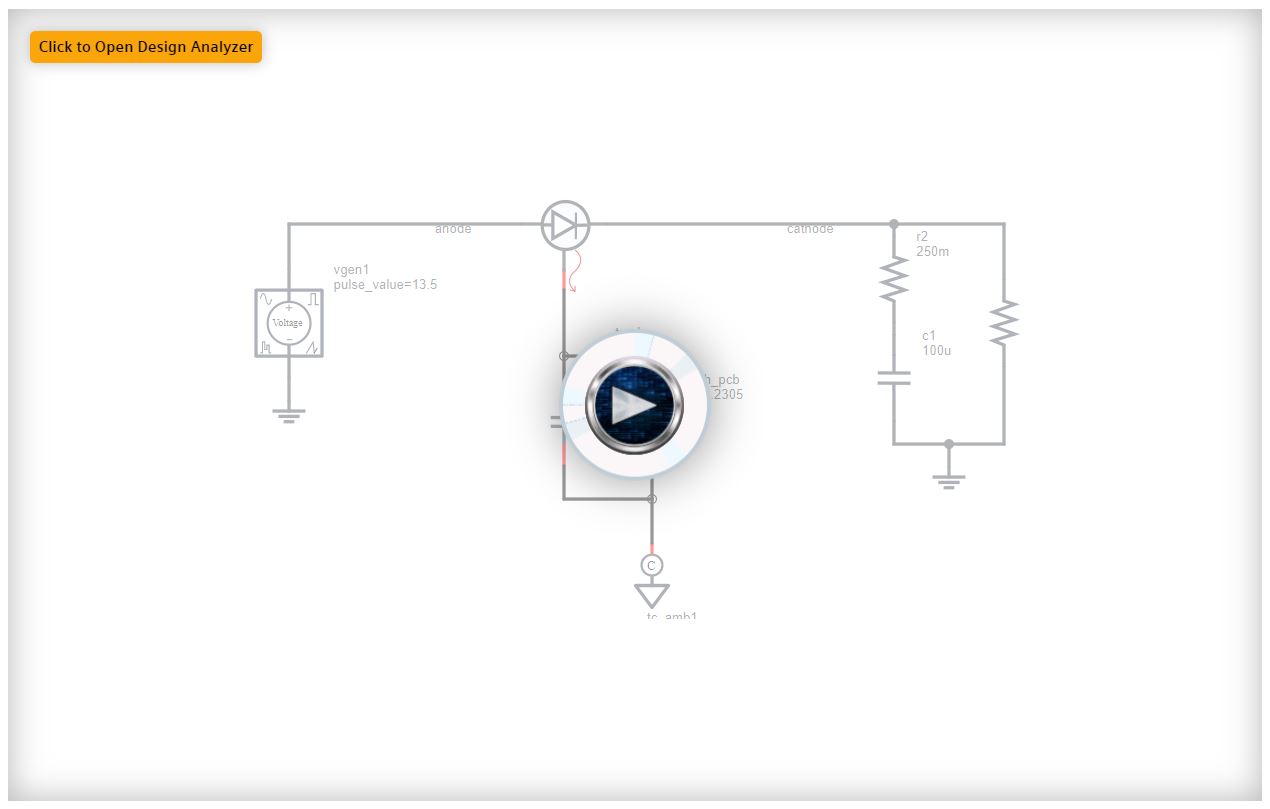
Figure 2. Launching the embedded simulation
The simulation will now open inside the interactive application note page.
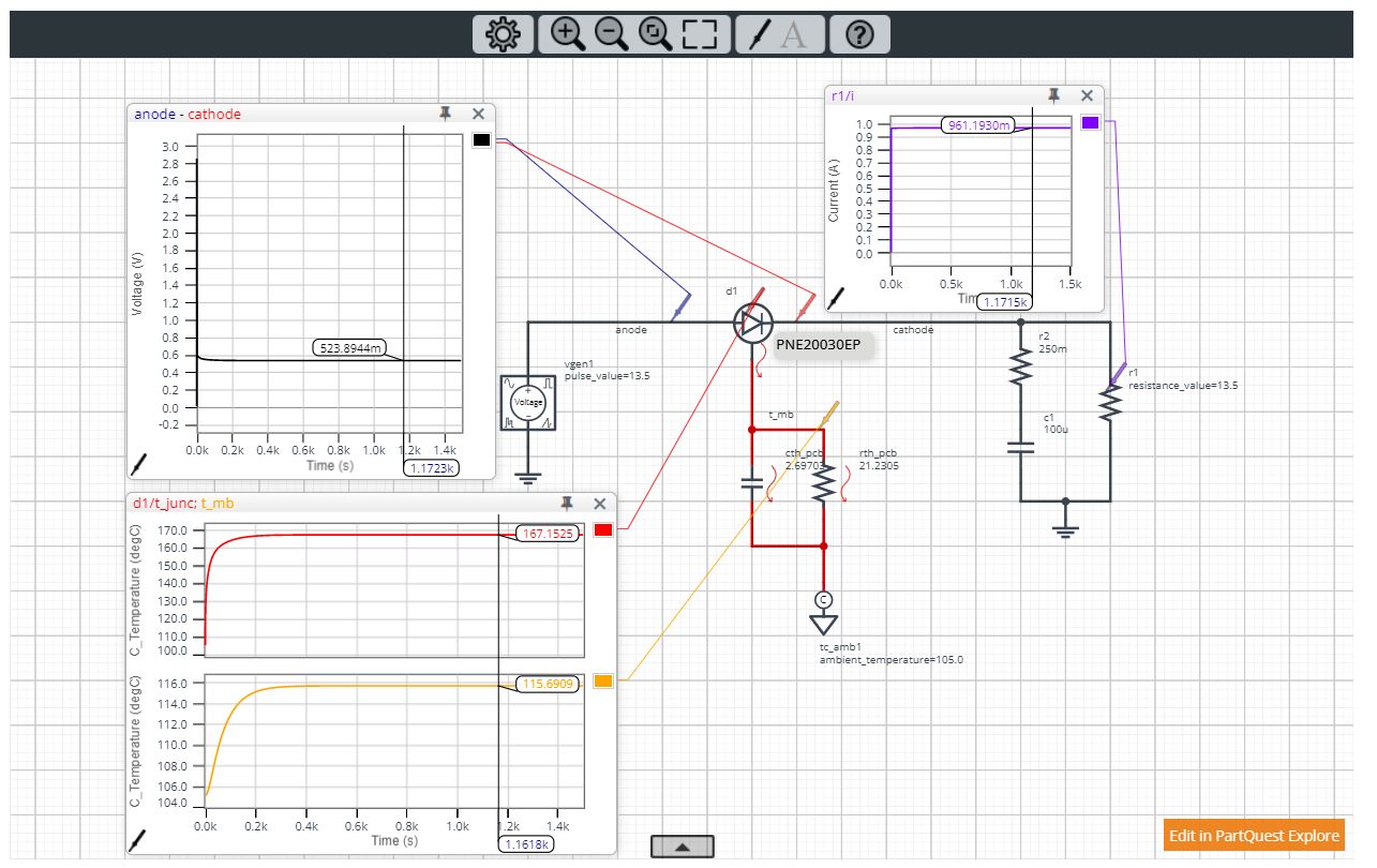
Figure 3. Simulation running inside the interactive application note
PartQuest Menu Icons
The main menu can be found at the top of the simulation.
Here you can change some design settings, alter your view of the simulation and add probes to display waveforms.
Clicking on the help icon will open a comprehensive guide to using the simulator.

PartQuest Explore Generic Components Library
- Analog Electronics
- Continuous Function Blocks
- Digital Electronics
- Magnetic and Electromechanical
- Mechanical
- Technology Converters
- Thermal and Electrothermal
- Three Phase Power
Some components for the above domains may be seen below.

Analog Electronics
- Resistors
- Capacitors
- Inductors
- MOSFETs
- Diodes
- Voltage and Current Sources
- Thermal and Electrothermal
- Others

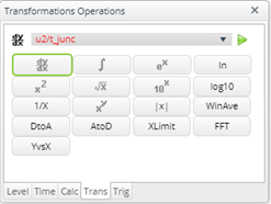
Continuous Blocks
- Subtraction Function
- Addition Function
- Multiplication Function
- Integration Function
- Others

Digital Electronics
- Digital Clock
- Digital Random Source
- AND, OR, Inverter, NAND Logic gates
- Multiplexer
- PWM
- Others

Magnetic and Electromechanical
- Air Gap
- Electromagnet
- Flux Function Generator
- Linear DCC Motor
- LVDT Sensor
- Windings
- Others

Mechanical
- Angle Sources
- Dampers
- Gears
- Inertias
- Weights
- Pumps
- Flux flow Generators
- Fluid reference
- Hydraulics
- Displacement Function
- Spring
- Others

Technology Converters
- Angle Conversion
- Angular Velocity Conversion
- Current Conversion
- Digital from/to Continuous
- Digital to/from Voltage
- Digital to Voltage (Differential)
- Displacement to/from Continuous
- Flux to/from Continuous
- Force to/from Continuous
- Temperature to from Continuous
- Others

Thermal and Electrothermal
- Cauer Thermal Network
- MOSFETs with Electrothermal
- Diode with Electrothermal
- LED with Electrothermal
- Electrical Power to Heat
- Resistor – Electrothermal
- Thermal Resistor
- Thermal Capacitor
- Thermal Radiation
- Others

Three Phase Power
- Transformer
- Three Phase Transformer
- Three Phase Voltage Source
- Clarke Inverse Transform
- Park Transform
- Others
Block explanation

Circuit schematic
The circuit shown in Fig. 5 a. is an Electrothermal circuit.
The electrical part is drawn with black wires whereas the thermal circuit is drawn with red wires. The part connecting the 2 domains is the Electrothermal model of the diode. More about other domains can be found in the Generic Components Library section above.
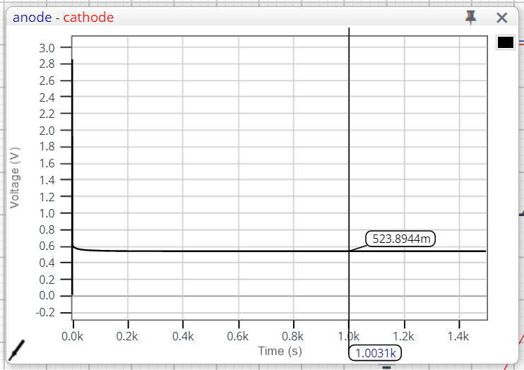
Waveform of the chosen point
The waveform shown in Fig. 5 b. is the anode - cathode voltage (VF) of the diode D1 (PNE20030EP) in the schematic of Fig 5 a.
The voltage, current, power dissipation and thermal waveforms can be displayed as detailed below.

Waveform viewer
There are 2 ways to view the simulation waveforms.
The first one is to view the waveform in the wave box displayed in the schematic. The other way is to check waveform in the wave viewer.
Set wavebox view
Click the probe and drag it into position. If the probe is at a wire or component terminal the default is to display voltage. If the probe stays at a component the required waveform(s) can be selected.
Note I(p1) means the current flow into port 1 of the device. I is default.

Figure 7. Current probing at R2
Zoom in and zoom out of waveform area
Left click and drag to the focus area you want to zoom in then release. The area in blue will be zoomed in. Right click then click View All, waveform will be zoomed out.
|
Figure 8. Area highlighted in blue to be zoomed in |
Figure 9. Zoomed in view of highlighted area |
Waveform menu
Right click on waveform, a menu will be displayed as shown below:
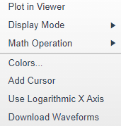
Figure 10. Waveform menu
Display Mode
Multi trace and Overlaid waveform views can be displayed in the wave box:
|
Multi trace view |
Overlaid trace view |
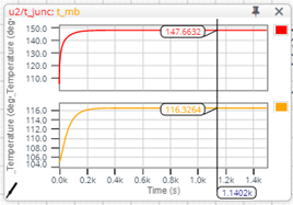
Figure 11. Display mode
Colors
Waveform colors can be customized.
Cursor
Click add cursor, the cursor will be added into waveform and relevant electrical reading will be displayed.
Download waveforms
Click download waveforms, the waveform data will be downloaded as a CSV (comma-separated values) file, which can be opened in Excel.
Wave viewer
Press Plot in viewer, the waveform will be displayed in wave viewer.
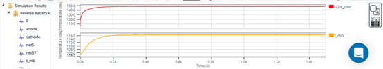
Figure 12. Waveform viewer
Click ![]() to open the waveform in a new window.
to open the waveform in a new window.
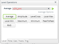
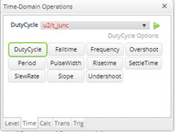
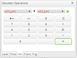
Math operations
Math operations are quite limited in wave box, only addition, subtraction, multiplication, and division can be used. It can be more useful when plotting waveforms in the viewer and using the waveform analyser.
 |
 |
 |
 |
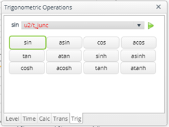 |
Figure 13. Function summary for embedded simulation
PartQuest Nexperia Library
Once in the PartQuest environment you may want to edit one of the many Nexperia designs to fit your own application specifications - or to create your own design using Nexperia parts. In either case, in order to find the relevant parts that you may require for your design, you will want to click on the partner button within the PartQuest library. You may see this in Fig. 15. There you will see Nexperia as one of the partners and by clicking on that other categories will appear from which, one can choose the NMOS Automotive MOSFETs seen in Fig. 16.
 |
 |
 |
||
| Figure 15. Navigating PartQuest components: Partner / Nexperia / NMOS | ||||
Moreover, a dropdown menu will show when choosing Automotive MOS with the different VDS(max) ratings from 30 V to 100 V and for each voltage rating there are the different packages: LFPAK33, LFPAK56, LFPAK56D, LFPAK56E, LFPAK88 and D2PAK.
 |
|
 |
 |
||
Figure 16. Selecting a Nexperia N-channel MOSFET by VDS rating and package
Once in the selected voltage menu and package one may select the desired RDSon range. An example may be seen in Fig. 17.
 |
| Figure 17. Nexperia N-channel MOSFET RDSon selection |
Within the RDSon menu one may be able to select the MOSFETs required for their design. Some examples of MOSFETs in the LFPAK56 and LFPAK88 packages may be seen in Fig. 17, in each menu a selection of MOSFETs is shown with the RDSon below 10 mΩ.
As an example, from LFPAK56 and LFPAK88 MOSFET selections seen in Fig. 17 a MOSFET was chosen from each category and placed onto the design sheet. These can be seen in Fig. 18 below as the BUK7Y1R7-40H and BUK7S1R0-40H.
 |
| Figure 18. Selected Nexperia N-channel MOSFET placed in design sheet |
Another method for finding the required Nexperia parts is by using the search in the PartQuest Library panel as shown in Fig. 19.

Figure 19. Fast library searching
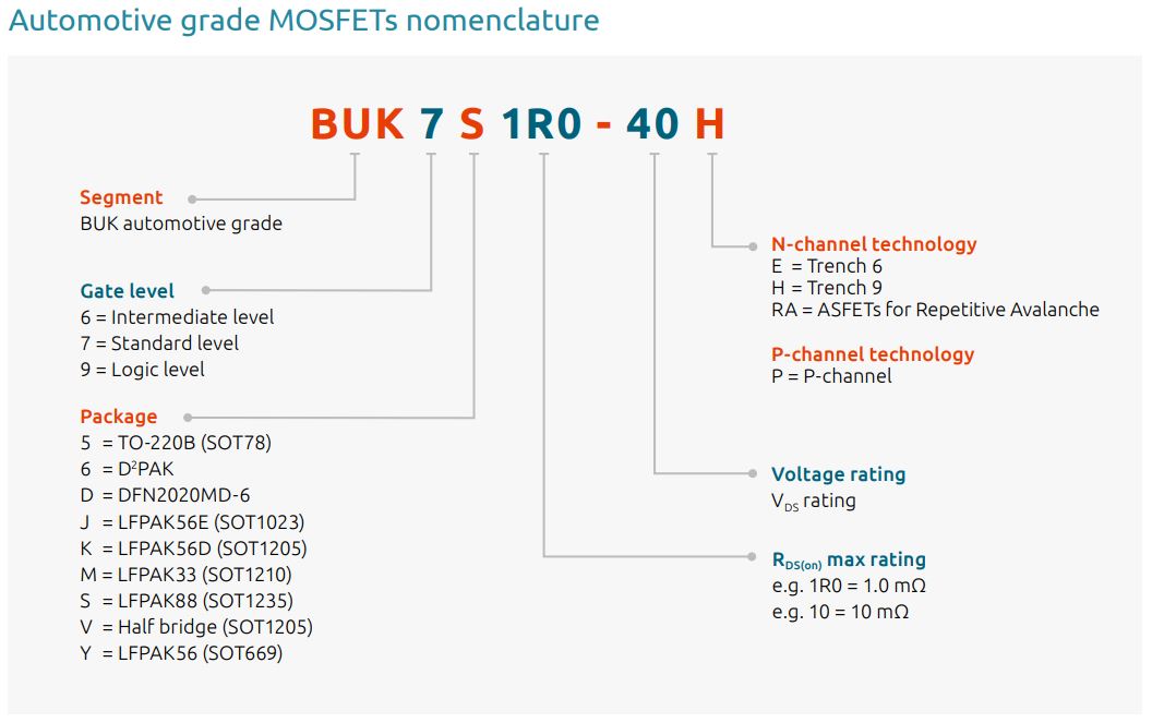
For fast library searches one should use the Nexperia naming rule for the specific components. An example is given below for the Nexperia Automotive MOSFETs.
Enter PartQuest Explore for further simulation functions
Click on Edit in explore.partquest.com (as shown in Fig. 3) to change the setting of the circuits. The main circuit will be shown in the centre. The circuit designers will be listed on the right of page.
Have fun with building and customizing PartQuest simulations yourself!
Nexperia Interactive Application Notes
Nexperia Interactive Application Notes
| Page last updated 24 November 2021. |