


Authors: Andrei Velcescu and Christian Radici; Application Engineers, Manchester
This interactive application note contains embedded Cloud based simulations to augment the text.
To open the embedded simulation, simply hover over the simulation image. Left click anywhere in the graphic area once the central play button changes in colour. This opens the schematic in the Cloud environment. See the interactive application note tutorial page for more details on how to use the simulations. See accompanying application note: AN50004.
1. Introduction
Within the automotive environment, Brushed Direct Current (DC) motors play an important role in the control of many applications within the car such as mirror folding control, window lifter, seat control, sunroof and power tailgate control, as well as oil, fuel and water pumps.

Figure 1. DC motor automotive applications
This interactive application note includes simulations of DC motor control and details the modeling of the motor used in the simulations.
2. Relay replacement in a power-folding mirror assembly
In modern automotive applications, an average of about 30 relays are used in a car. Driving a relay is simple, and the internal resistance of the connection can be very low. However, compared with relays, MOSFETs have obvious advantages in noise, service life, miniaturization and reliability. Therefore more and more manufacturers consider using MOSFETs to replace relays.

Figure 2. Relays replaced with MOSFETs
Fig. 2 a) is a motor scheme that mainly uses relays for motor drive. The direction of the motor rotation is selected by the contact of the relay. However, the relay cannot control the current of the motor, so it still needs to be connected to a MOSFET to control the current, so as to meet the functional requirements of anti-pinch.
Fig. 2 b) is a scheme that directly uses MOSFETs to drive the motor. The direction of motor rotation can be controlled using only one MOSFET, while the other MOSFET can be switched by PWM to control the motor current.
A Nexperia demo application which showcases how MOSFETs may replace relays may be seen in Fig. 3. These were used in controlling the mirror power-folding mechanism using 12 V or 24 V H- bridge DC motor control. As can be seen, the relays were replaced with MOSFETs in the LFPAK33, LFPAK56D and LFPAK56 small SMD packages.

Figure 3. Relay replacement demo board
By using any of the power MOSFET variants, there will a space reduction of up to 1:100 in terms of volume, 1:10 in terms of board area and 1:20 in terms of weight. This is depicted by the orange highlighted area in Fig. 3 versus the yellow highlighted area. In terms of performance, the LFPAK MOSFETs will offer high current handling for locked rotor protection, high reliability and full Automotive Qualification AEC-Q101. Lastly, the copper clip within the LFPAK MOSFETs offers a good thermal performance.

3. Brushed Direct Current motor modelling
The DC motor is a common actuator in the automotive environment and in order to understand how to better choose the MOSFETs controlling it and their ratings as well as obtain the wanted behaviour from the motor, it was modelled as shown in Fig. 4. Moreover, as it will be seen later, the motor characterisation was conducted in order to have a representative example.
Click below to enter the simulation.
Simulation 1.
In simulation 1, a DC motor is connected to a DC voltage source of 5 V. This shows that the rotational speed of this particular motor is 103.2 rad/s. Considering the inner structure of the DC motor one can consider its armature circuit, (as can be seen in Fig.4). This contains its electric resistance (Ra), inductance (La) as well as back EMF (e). Moreover, the rotor mechanical constants are also shown as: motor torque (T), rotor angle (θ) and rotor inertia (J). Taking these into consideration and applying some circuit analysis techniques such as Kirchhoff’s voltage law, gives Eq. 1 below:
(Eq 1) 
In this case V is the input voltage to the DC motor and the one supplied by the H-bridge which is formed by 4 MOSFETs within 2 half-bridges in order to obtain bi-directional control.
Considering the magnetic field as constant, the torque produced by the DC motor will thus be proportional to the armature current and the motor torque constant KT. This may be seen in Eq. 2 below:
(Eq 2) 
Moreover, the back EMF is proportional to the rotor velocity dθ/dt and the back EMF constant K , as shown in Eq. 3 below:
(Eq 3) 
As it is considered that the torque and back EMF constants are equal, the following equality may be given: KT = Ke = K.
Based on the above equations the motor output torque and speed may be approximated by knowing the motor constants. This may be found using the motor data sheet or by measurement. More information about how some of the constants were determined for an example DC motor will be given later.
4. H-bridge theory
The H-bridge, also known as full-bridge, is an electronic system consisting of four switches and capable of creating a bidirectional current and reversible voltage across its load. This function comes in handy when driving a motor because it allows to change the direction of its rotation and, if the application allows it, even to use it as a generator. This circuit is used in many systems such as in inverters (DC/AC), regulators (DC/DC) and class-D amplifiers.
The H-bridge can be thought of as composed of two half-bridges used simultaneously. The half-bridge is capable of bi-directional current but not reversible voltage and therefore, it is mainly used in motor drive applications with single direction motors such as oil pump motors and small fans.
4.1. Modes of switching
The easiest and most popular way to drive a DC motor using a H-bridge is by using pulse width modulation (PWM). Here the MOSFETs are switched at a constant frequency with a control signal having variable duty cycle. This allows the average voltage across the motor to vary and thus control the rotor angular velocity. The MOSFETs in a H-bridge can be switched in different sequences to provide the desired voltage polarity. There are two common modes: bipolar and unipolar.

The bipolar drive allows two MOSFETs to be switched ON at a time. For example for positive current (from node A to node B) both Q2 and Q3 are turned ON. Whereas, for negative current, Q1 and Q4 are turned ON. The direction of the current is chosen by activating one or the other couple of FETs while applying a voltage across the motor that varies between VDC and -VDC, with an average value that depends on the duty cycle (δ), see Fig. 5.
A time delay, known as dead-time, must be set between the turning OFF of one pair and the turning ON of the other pair, in order to avoid cross-conduction (or shoot through), that is shorting the supply.
Due to the magnetic field build up in the motor, during the delay phase some current will continue to flow, even though all the devices are turned OFF, by recirculating through the MOSFETs body diodes.

The unipolar drive scheme, instead, allows for the current to be regulated by keeping ON one right side MOSFET (Q2 or Q4) while switching only one left side MOSFET(Q3 or Q1). In its simplest form it allows for the elimination of the dead time which reduces the complexity of the driver circuit. For the same reason described in the bipolar drive some current will be forced to flow through one of the MOSFETs body diode when the switching MOSFET is turned OFF, see Fig. 6.
If we assume Q3 switching and Q2 turned ON, then when the former is switched OFF the current will flow through Q1 body diode. In order to decrease the loss caused by the diode voltage drop, Q1 can be switched ON while Q3 is OFF. In this case a proper dead-time constraint must be respected.
One of the major difference with the bipolar drive scheme is the fact that the voltage across the motor will have an amplitude of only VDC. As a consequence the peak of the ripple current through the motor ends up being half of the one found for the bipolar case, thus leading for lower losses in the motor itself
5. Circuit simulation
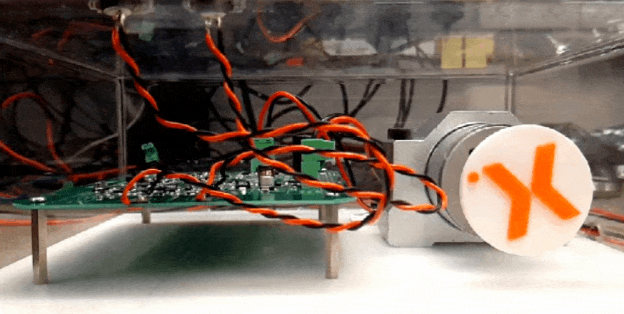
Based on the technical note TN90002 and on the hardware seen in Fig. 7, simulation 2 was created. This focuses on the H-bridge part containing 4 Nexperia LFPAK56 MOSFETs, the BUK7Y7R8-80E.
|
Figure 7. Experimental setup with motor and control board |
Figure 8. Schematic of motor drive circuit simulation |
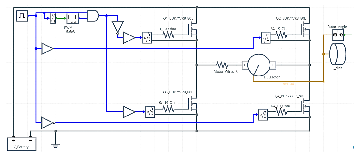
The simulated circuit may be seen in Fig 8. This focused on the behaviour of the MOSFETs and thus the logic circuit was approximated using a Digital Pulse Source, a Digital Inverter, AND gates, Buffers and Digital to Voltage blocks. Additionally the PWM generators were set to one of the frequency options used in the TN90002, 15.6 kHz. Similarly, 10 Ω gate resistors were used.
6. Logic and MOSFET gate signals
Investigating the schematic shown in Fig. 8 from left to right, one may see the Digital Pulse Source. This is used as an input which dictates the direction in which the motor rotates and the time for which this happens. This input signal, seen as the green trace in simulation 2 replaces a person’s interaction when using the buttons, as in TN90002. The logic signal is set to 1 for 150 ms. In this manner the motor is rotating clockwise. Due to this, Q2 is fully switched ON for this duration and Q3 is switched ON and OFF using the PWM generator. Moreover, Q1 was pulsed with the inverted PWM signal delivered to Q3 in order to reduce the voltage drop on the diode of Q1. In this manner the top MOSFET, Q1, is freewheeling the motor current. If this was not the case and Q1 was OFF the losses would be higher. The control signals for Q1 and Q3 may be seen in simulation 2 as the blue and red traces whereas the ones for Q2 and Q4 may be seen as the light blue and purple traces.
Click below to enter the simulation.
Simulation 2.
As mentioned, due to Q3 switching, a dead time was also required. Considering the signals of Q1 and Q3 as well as for Q2 and Q4 from simulation 2 the used dead time was 2 µs, whereas the one set within the TN90002 was 2.5 µs. This was implemented using the Buffer blocks seen in Fig. 8. Moreover, the 15.6 kHz PWM signal was set to a duty cycle of 12.5%.
Once the logic driving signal reached the Digital to Voltage Converter, a 10 V signal was generated in order to switch ON and OFF the four BUK7Y7R8-40E MOSFETs of the H-bridge.
Click below to enter the simulation.
Simulation 3.
In simulation 3 above, the gate voltages of the respective MOSFETs of the H-bridge may be seen. The MOSFETs forming the left half-bridge, Q1 and Q3 have been switched using PWM whilst Q2 and Q4 have been turned ON or OFF fully for the respective durations. Notice the plots of VGS_Q1 and VGS_Q3 , one can again see the dead time implementation.
Simulation 4 below shows the drain-to-source voltages of the MOSFETs within the left half-bridge may be seen, as well as their respective drain currents. These have been shown for a time window of approximately 100 µs in order to focus the attention to the switching behaviour. Moreover, by multiplying the drain-to-source voltage of Q3 by its drain current, seen in simulation 4 the instantaneous power dissipation was obtained. This data can be averaged and used for the derivation of the FETs thermal behaviour, via a suitable RC network (Foster or Cauer). In order to find the average or rms power one can consult the Wave Viewer and Math operations sections within the tutorial page.
Click below to enter the simulation.
Simulation 4.
7. Motor characterisation and constants
In order to simulate the behaviour of the H-bridge controller demo previously explained the motor characteristics had to be extracted so that for a specified PWM duty cycle the rotor speed in the simulation would match the one of the real application.
The rotor dimensions were measured and by approximating its shape to a cylinder its moment of inertia was found using Eq. 4 where m = rotor mass and r = rotor radius:
(Eq 4) 
For this particular motor the rotor was measured to weigh 220 g and to have a radius of approximately 17 mm, thus yielding an approximately 3.15x10⁻⁵ kg·m2 moment of inertia. Additionally the plastic disc was found to have a moment of inertia of approximately 3.5x10⁻⁶ kg·m2. By adding the two, the total inertia was found to be 3.5x10⁻⁵ kg·m2.
Using a DMM, the winding resistance was measured to be approximately 1.5 Ω. This was also found by conducting a motor stall test and from the step response of the DC motor seen in Fig 9.
(Eq 5) 

Figure 9. DC motor step response
Additionally the electrical time constant of the motor 𝜏, is found using Eq 6. At 63.2% of its steady state value the current in Fig. 9 reaches approximately 1.5 A (Eq 7, Eq 8) This happens at approximately 0.39 ms. Using 𝜏 and the value obtained for the motor winding resistance the winding inductance was found to be approximately 600 µH.
(Eq 6) 
(Eq 7) 
(Eq 8) 
By conducting several measurements the motor’s rotational speeds were found at different voltages as well as the currents and voltages. From these, the motor’s KV and Ke values were inferred and thus the KT value was found to be approximately 0.045 Nm/A.
For the DC motor the following are considered as motor constants (Eq 9):
(Eq 9) 
Lastly, another important parameter was the viscous drag which was found to be approximately 0.0001 Nm/(rad/s). At this stage the motor was characterised and thus expected to behave as the real one presented in the technical note TN90002.
When tested, the real system was found to achieve a rotational speed of approximately 6 RPS or 360 RPM which translated to approximately 37.7 rad/s. The board supply voltage used was 20 V, the PWM frequency, 15.6 kHz and a duty cycle of 12.5%.
Simulation 5.
In the above simulation the motor steady state velocity may be seen. The rotational speed was found to be approximately 40 rad/s which is similar to the 37.7 rad/s seen in the real application from Fig. 7. Additionally the motor current and torque for the full simulation period of 150 ms could also be seen and further investigated in the simulation window. In simulation 5 one may see the motor voltage and current for a few PWM periods. These results are similar to the oscilloscope results of the real system in Fig. 10.
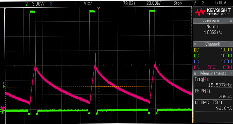
Figure 10. Oscilloscope screen shot of motor voltage and current
8. MOSFETs recommendations by application
Some MOSFET recommendations are given below for applications using half-bridge and H-bridge configurations for motor control. The aimed applications are: mirror folding control, window lifter for anti-pinch function, seat control, sunroof and power tailgate control as well as fuel, water and air pumps.
8.1. Power folding mirror
Some MOSFETs that are recommended for this 12 V or 24 V H-bridge application are summarised in Table 1.
8.2. Window lifter for anti-pinch function
For this application the MOSFETs and system may be required to have low on-state losses, overcurrent protection, low thermal resistance and low thermal impedance as well as the need to be integrated into a relative small board area. The control uses PWM with frequencies ranging from 10 to 20 kHz. Motor currents of around 2 A to 5 A are expected for normal operation and operation around 10 A for shorter periods of time. In locked rotor cases, the current demand is much higher and may reach 30 A for periods ranging from 200 ms to 1 second.

8.3. Window lifter for anti-pinch function
For this application the MOSFETs and system may be required to have low on-state losses, overcurrent protection, low thermal resistance and low thermal impedance as well as the need to be integrated into a relative small board area. The control uses PWM with frequencies ranging from 10 to 20 kHz. Motor currents of around 2 A to 5 A are expected for normal operation and operation around 10 A for shorter periods of time. In locked rotor cases, the current demand is much higher and may reach 30 A for periods ranging from 200 ms to 1 second.
8.4. Seat control
In the seat control application two motors are sometimes required, one for the forward and backwards seat adjustment and another for the backrest support adjustment. A schematic of the two H-bridges may be seen in Fig. 11.
More complex circuits may be encountered in high end car models where several other motors are required in order to control things such as height, the left and right chair sides and the head rest position.
8.5. Sunroof and power tailgate control
There are a few motors in sunroof and power tailgate applications. The motors can control the sunroof forward/backward and up/down, therefore the driving stage is required to allow bidirectionality. Both brushed and brushless DC motors can be used in this application, the former driven by a H-bridge (Fig. 12) and the latter using a multiphase half-bridge (Fig. 13). The maximum current needed for this kind of application may be around 10 A for the more power hungry ones.
 |
 |
| Figure 12. H-bridge MOSFETs in sunroof motor control | Figure 13. 3-phase MOSFETs in sunroof motor control |

8.6. Fuel, water and air pumps
There are a number of pumps used in automotive applications, such as fuel, water and air pumps. Both brushed and brushless DC motors can be suitable for this application. For the former a simple half-bridge structure can be used (Fig. 14). In some small current load applications, the recirculating FET can be replaced by a Schottky diode. For brushless motor a more comple structure of 3-phase bridge is required Fig. 13. In this case the difference in complexity and number of components can be quite stunning.
Since different motor applications have different power levels, from a small 30 W pump to a 300 W intake fan, the demand for power MOSFETs varies. Due to the many advantages of brushless motors more and more small water pump motors have now adopted the brushless scheme. Here, due to the large number of MOSFETs, we recommend the use of smaller packages such as the LFPAK33 and the LFPAK56D (dual devices) MOSFETs for motor drive. The 40 V device is suitable for the application of most 12 V motors. The specific model selection calls for the appropriate packaging and internal resistance, according to the load power of the motor and the overall cooling requirements of the module. Standard level VGS threshold is suggested.
Applications |
System recommendations |
MOSFET characteristics |
MOSFET recommendations |
|---|---|---|---|
| Power folding mirror |
|
|
BUK7Y3R5-40E BUK7K6R2-40E BUK9M14-60E |
| Window lifter for anti-pinch | BUK7Y4R4-40E BUK7K6R8-40E BUK7M6R0-40H |
||
| Seat control | BUK7Y3R5-40E BUK7M6R0-40H BUK7K6R2-40E |
||
| Sunroof and power tailgate control | BUK7Y3R5-40E BUK7Y4R4-40E BUK7K6R2-40E BUK7M6R0-40H |
Table 1. Recommended MOSFETs for automotive motor control applications
9. Summary
The main applications of DC motors and MOSFET recommendations have been discussed.
Nexperia offers many suitable options for the most popular applications. DC motor modelling and characterization has been presented, which can be used to better predict the performance of the driving circuitry and the selection of the necessary components. Theoretical and practical notions of H-bridge have been outlined, in particular methods of implementing PWM, motor ripple current, MOSFET dissipation and switching frequency selection.
Finally an example from the technical note TN90002 has been presented. Its main features and operational concept have been summarized and further aspects clarified in more details. Interactive simulations of this system have been embedded into this application note to assist in understanding the driver and power stage operation.
PartQuest embedded Cloud simulations were used in this interactive application note.
| Page last updated 28 September 2021. |